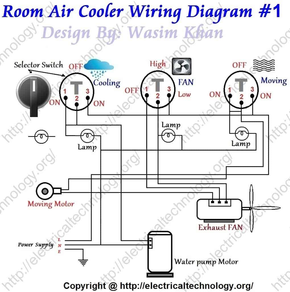
Room Air Cooler Wiring Diagram 1
Electrical Technology 2 Less than a minute Room Air Cooler Wiring Diagram # 1 Note: Check the Room Air Cooler Wiring Diagram # 2. Room Air Cooler Wiring Diagram # 2 (With Capacitor marking and Installation) Room Air Cooler Wiring Diagram # 1 Click image to enlarge.

Air Cooler Connection Diagram Wiring23
Step two: Preparing the pump head. The pump head of the iCUE RGB ELITE Liquid CPU cooler comes pre-installed with the Intel mounting bracket. If you are using an AMD system, you will need to replace the mounting bracket with one that is AMD-compatible. To install AMD mounting brackets on the pump head: Remove the thermal paste plastic cover.
Cooler Connection Diagram Headcontrolsystem
Cooler Connection Blog; Contact; Link To Us; Employment Opportunities & Careers; Additional Links; Tradeshow Schedule; Site Map; Get A Quote; Make a Payment; 800.521.COOL(2665) Products. Why U.S. Cooler Walk-Ins; Walk-In Coolers; Walk-In Freezers; Walk-In Cooler / Freezer Combo;

3 Wire Cooler Motor Connection Diagram Wiring Diagram Schematic
Wiring Layout. Connectors: 4 x Female Peripheral Molex. 1 x Male Peripheral Molex. 2 x Male 2 pin LED Molex. 2 x Female 2 pin LED Molex. Instructions: 1) Connect all 4 female peripheral molex into your power supply's 4 male peripheral molex. 2) Connect the 2 male 2pin LED connectors into the 2 female 2pin LED connectors.

Wire Cooler Motor Wiring Diagram And Connection Procedure, 49 OFF
8wires is a fast-growing startup in the field of machine learning and data analytics. our main value proposition is to answer the business key questions and distill the knowledge acquired to our clients in a transparent, efficient and trusted way, covering the whole data science and architecture value chain, from data integration and preparation to the model deployment. for that reason, we are.

COOLER COMPLETE WIRING! COOLER CONNECTION WITH REGULATOR SWITCH YouTube
Yes anything that is needed for the CPU cooling should be plugged into any and all CPU Fan Headers or PUMP Fan headers that you have. SO what's happening right now in your rig is that when the CPU heats up to a certain temp it adjusts the volts to increase the Fan speed to increase airflow. Now instead of it doing that for your Cooler fans its.

️Champion Swamp Cooler Wiring Diagram Free Download Gmbar.co
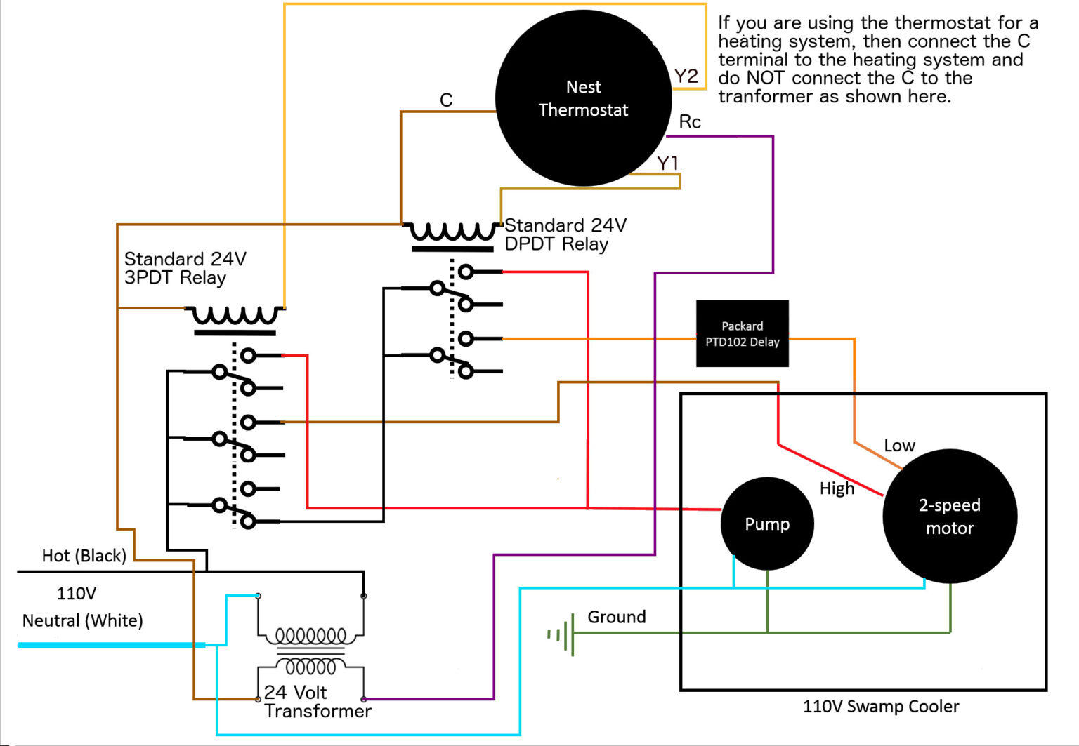
Typically, an evaporative cooler motor wiring diagram includes symbols and color codes that indicate the various wires and their connections. These diagrams may vary depending on the specific model and manufacturer, so it's important to refer to the correct diagram for your particular system.

4 Wire Cooler Motor Connection Diagram Two Switch Wiring Connection Diagram Air Cooler Wiring
Cooler complete wiring with fan motor connection & water pump motor connectionIn this video we explain cooler wiring with fan motor and for speed control we.

4 Wire Cooler Motor Connection Diagram
Connect the adapter to CPU Fan 1. CPU Fan 2 / OPT can be left unused. Two Radiator Fans without Y-Splitter: Connect one fan to CPU Fan 1 and the other to CPU Fan 2 / OPT. Four Radiator Fans via Y-Splitters: Connect one adapter to CPU Fan 1 and the other adapter to CPU Fan 2. PUMP:
Cooler Motor Connection With Regulator Multi Speed Cooler Connection
Welcome to @ElectricalTechnologies Today we learn complete Room Air Cooler Wiring Diagram.An air cooler works on the principle of evaporative cooling wherein.
+-+Copy.jpg)
Room Air Cooler Wiring Diagram 2. (With Capacitor marking and Installation) Electrical
Cooler wiring connection | 3 speed motor connection 33,094 views 242 In this video we have taught you how to repair cooler in your room. 3 speed motor can repair the cooler. Air swim.
Cooler Motor Connection With Regulator Multi Speed Cooler Connection
How to Wire a Walk-In Cooler Wiring a walk-in cooler is an important step in setting up a functional and efficient cooling system. Proper wiring ensures that the cooler operates safely and all the components function correctly. Here are some steps to wire a walk-in cooler: 1. Plan the electrical layout
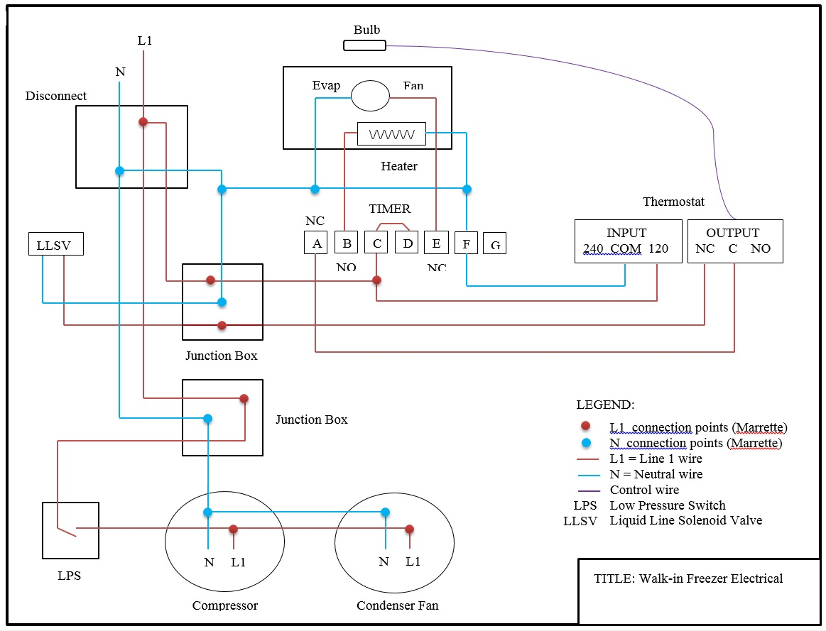
Walk In Freezer Wiring Diagram Wiring Diagram
3 pin and 4 pin Fan Wire Diagrams. 3 pin Fan Connections. *cable coloring varies from fan to fan. Pin Name. Color. Color. Color. Color. 1.

Single speed cooler motor winding 4 wire cooler motor connection diagram
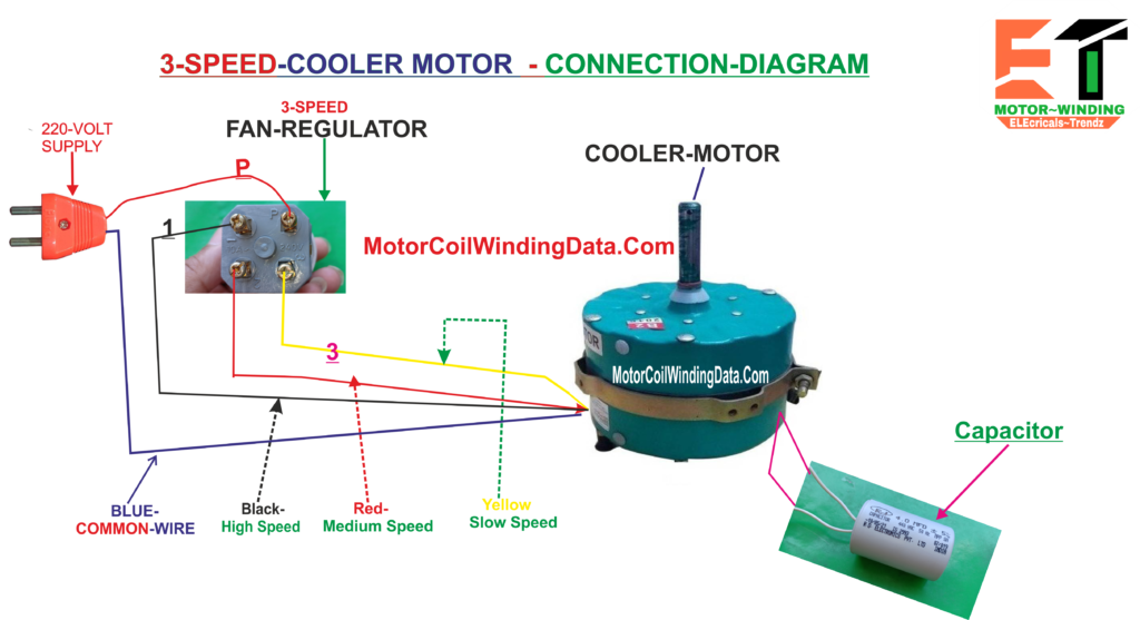
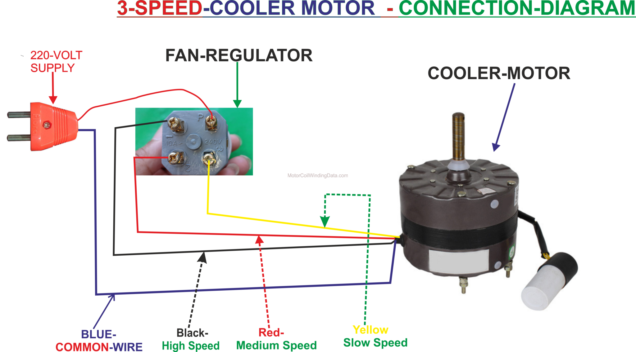
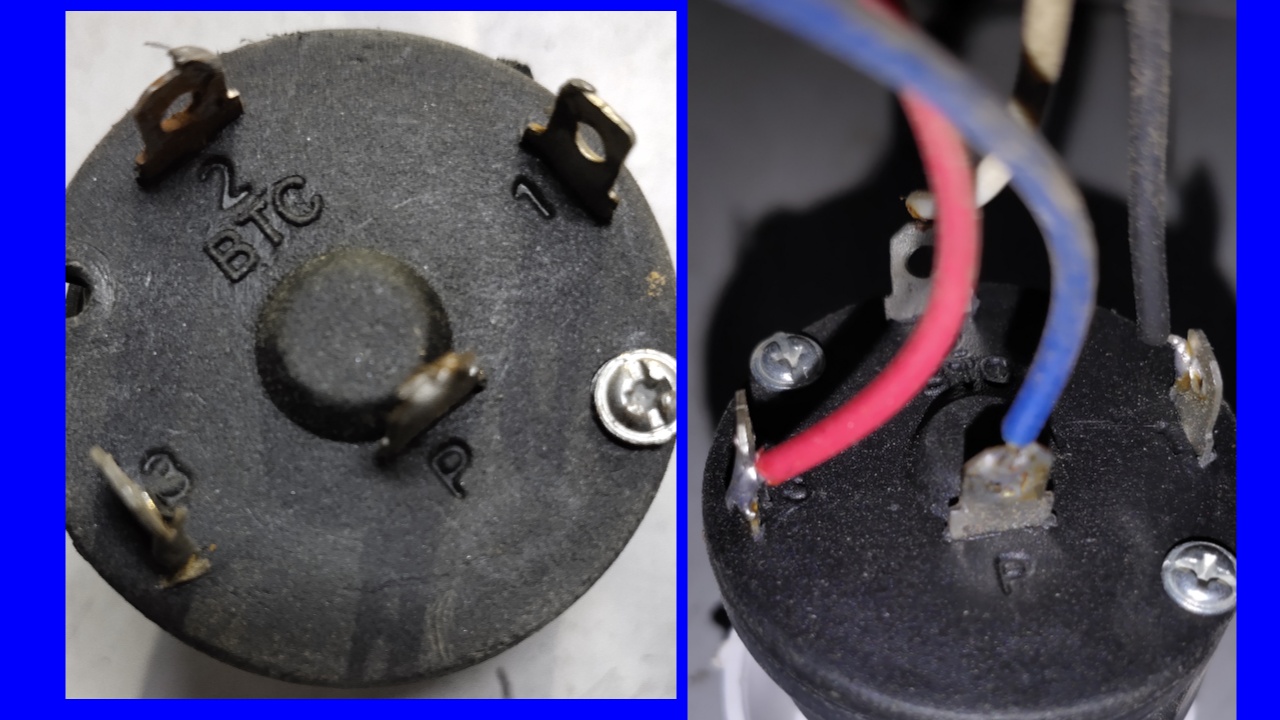
3 Speed Cooler Motor Connection. In a 3 Speed Cooler Motor, the motor windings carry a total of 6 WIRES, with one wire as the Common wire, and the other as 3 speed, and two capacitors.The blue wire is the common wire.The black wire is of high speed.The red wire is a medium speed, and the white wire is slow speed, in which the cooler runs the slowest, and the black wire runs the cooler fastest.
How to make wiring connection of air cooler with rotary switch. Benefits for all peoples, R. O
Proper installation and wiring are essential for the optimal functioning of the evaporative cooler. The wiring diagram of an evaporative cooler includes various components that work together to ensure efficient cooling. These components include a motor, pump, thermostat, and junction box. The motor powers the fan, while the pump circulates.
electrical How to wire a relay for an evaporative cooler to a thermostat? Home Improvement
Installation Guide U. S. Cooler walk-in cooler and freezer installation video. Watch on Click the following to view U.S. Cooler® Installation Guide. These plans will guide you through the steps of building / assembling your cooler or freezer unit. U.S. Cooler Installation Manual Installation Instructions General: